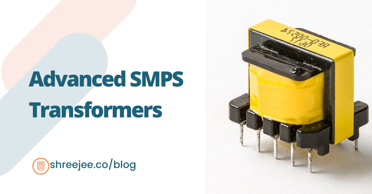
Switch-mode power supplies (SMPS) are crucial in powering modern electronic devices, providing efficiency and compactness. At the heart of these systems are transformers that efficiently convert and isolate electrical energy.
Understanding SMPS Transformers
SMPS transformers operate at high frequencies, ranging from 20 kHz to several MHz. They convert electrical energy from one voltage level to another while providing galvanic isolation, crucial for ensuring efficiency and reliability in various electronic devices.
Designing SMPS Transformers
Designing an SMPS transformer involves several critical steps: defining power supply parameters, selecting core materials, and calculating turn ratios and winding configurations. The prices of these transformers vary based on their power rating, core material, and design complexity. They range from a few rupees for low-power units to several thousand rupees for high-power industrial applications.
Tools and Methodology for Designing SMPS Transformers
Engineers use specialized tools like SIMPLIS and MATLAB to model and optimize transformer designs before prototyping. These tools predict performance characteristics such as efficiency, temperature rise, and electromagnetic interference (EMI), ensuring robust designs.
A novel design methodology for SMPS transformers considers high-frequency effects in solid round windings, maximizing power density. This method is especially useful for forward converters, where round wire shape and high-frequency currents greatly affect losses. This methodology includes comprehensive transformer models considering core and winding losses, thermal behavior, and the operating BH loop to avoid core saturation.
Core and Winding Material Considerations
The choice of core material and winding configuration is crucial. Common core shapes include EE, EFD, ETD, EP, PQ, RM, ER, Pot, Toroid, UU, and UI. Each shape has unique benefits for minimizing core losses, reducing EMI, or improving thermal performance.
Core Materials:
- Ferrite Cores: Engineers prefer ferrite cores for high-frequency applications because they have low eddy current losses
- Powdered Iron Cores: Offer high saturation flux density but have higher core losses at high frequencies.
Winding/Conductor Materials:
- Copper Wire: Known for its high conductivity. Various types include:
- Enameled Copper Conductor as per NEMA Standard: Provides insulation and high thermal resistance.
- Tex–E Wires (Triple Insulated Wires): Offer enhanced safety and insulation.
- Round Litz Wire & Twisted Wire: Reduce skin and proximity effects, improving efficiency at high frequencies.
- Copper Foil: Copper foil in SMPS transformers helps reducing high-frequency losses caused by skin and proximity effects. Planar transformers with copper foil windings offer reduced profile height, improved thermal management, and consistent performance.
Balancing core and winding losses is crucial, especially in discontinuous mode, where core loss can become a limiting factor.
Using cores with large, wide windows can minimize winding layers and reduce AC winding resistance. In continuous mode operation, focusing on core size and material is key to achieving high efficiency, as AC losses are minimal.
Applications of SMPS Transformers
- LED Lighting: Enable efficient power conversion and dimming capabilities.
- Welding Instruments: Provide stable, high-current outputs.
- Telecommunications: Deliver reliable power in compact designs for base stations and networking equipment.
- Medical Equipment: Ensure stable and noise-free operation for sensitive devices such as MRI machines and patient monitoring systems.
- Battery Chargers: Provide efficient and controlled charging for electric vehicles and portable electronics.
- Data Centers: Power uninterruptible power supplies (UPS) and server power supplies.
- Aerospace and Defense: Power avionics, radar systems, and communication equipment under harsh conditions.
- Industrial Automation: Power programmable logic controllers (PLCs), motor drives, and robotic systems in automated manufacturing processes
Testing SMPS Transformers
Testing an SMPS transformer involves key procedures:
- Continuity Testing: Ensures proper winding connections.
- Resistance Measurement: Detects short circuits or open windings.
- Inductance Measurement: Verifies winding inductance using an LCR meter.
Accurately measuring power losses in high-frequency transformers is critical for optimizing SMPS efficiency. A practical method is to use a working power converter model to assess transformer losses under real conditions. Engineers can determine core loss by connecting an identical transformer in parallel and measuring the additional input power. Additionally, thermal resistance is calculated by monitoring temperature rise and dissipated power.
Exploring Transformer Topologies
Engineers use different SMPS topologies for specific applications:
- Flyback Transformers: Ideal for low to medium-power applications, offering simplicity and cost-effectiveness. Research highlights the use of flyback converters in high-voltage power supplies (HVPS), showing that duty cycle and switching frequency are crucial in determining the output voltage.
- Forward Converters: Suitable for higher efficiency and continuous power transfer, requiring careful design to ensure optimal core utilization and minimize losses.
- Push-Pull Transformers: Best for higher power applications, offering better efficiency and reduced EMI.
- Gate Drive Transformers: Used for isolating gate drive signals in high-power switching applications.
- Resonant Converters: Achieve zero-voltage and zero-current switching, reducing switching losses and improving efficiency.
SMPS Transformer Pinouts
The pinout configuration of an SMPS transformer defines the connections for primary, secondary, and auxiliary windings. Proper pinout configuration is essential for correct functionality and integration into the circuit, preventing potential damage from incorrect wiring.
Understanding Transformer Nomenclature
The nomenclature of SMPS transformers, such as 70-0-70 10A or 12-12-5 8A, indicates their voltage and current ratings. For example, 70-0-70 10A means a center-tapped transformer with 70V on each side of the tap and a 10-amp current rating. Similarly, 12-12-5 8A indicates dual 12V secondary windings and a 5V winding, each capable of delivering 8 amps.
Shreejee Electronics integrates advanced design methodologies and high-quality materials to ensure its SMPS transformers meet the highest standards of efficiency and reliability. For more information or to discuss your specific needs, please contact Shreejee Electronics.
