
When measuring AC currents and voltages of high magnitude, we often take for granted clamp and amp meters. However, the question is, how are these portable measuring instruments able to step down the magnitude to a standard range instrument? How can the original magnitude be determined by just multiplying the result with the transformation ratio?
In this blog post, we shall learn more about such instrument transformers. Specifically, the current and potential transformers that transform AC currents and voltages whose turn ratio is accurately known.
Current Transformer
A conventional CT or Current Transformer is a passive magnetic device that allows measuring current by stepping down the current on the secondary side.
- In practical terms, it reduces high voltage currents to a much lower value to provide a convenient way of safely monitoring the actual electrical current flowing in an AC transmission line.
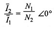
- Generally, it is any regular transformer with a 1:XXX turns ratio.
- As CT drives current through an infinite impedance, it will produce a high voltage when open-circuited.
- When the current is constant, resistance will be directly proportional to the voltage.
As mentioned, CT has only one or very few primary turns.
Testing a Current Transformer
Some of the most common tests carried out can easily be performed with the CTs mounted in the switchgear include:
- Polarity Check,
- Ratio Check and
- Magnetization Curve.
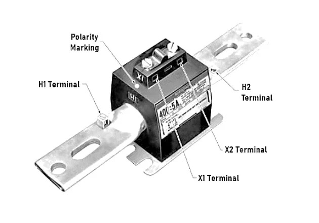
Polarity Check
This check is necessary to see the relative polarity of the primary and secondary terminals when terminals are not marked or to establish the correctness of the marking if already marked.
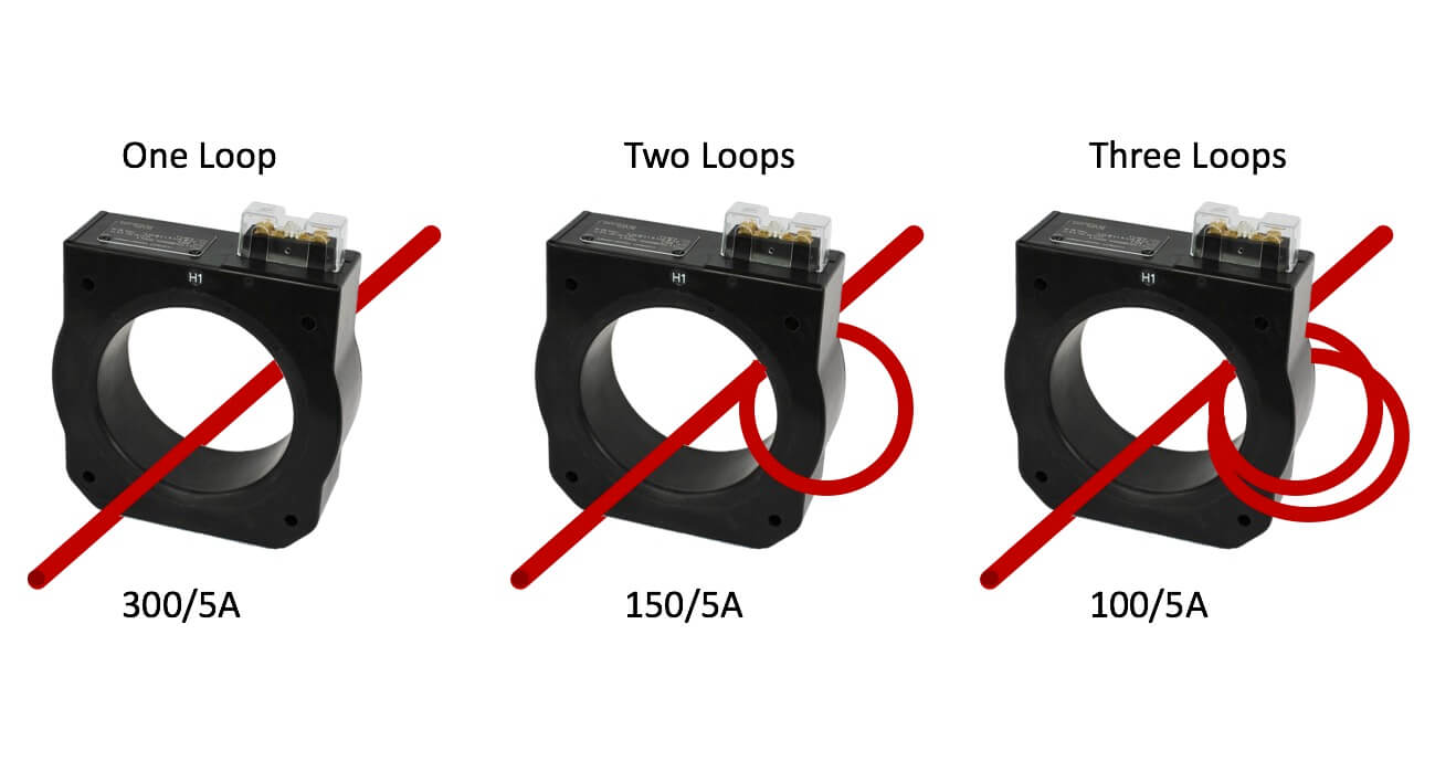
Ratio Check
A ratio check is usually carried out during the primary injection tests. The ratio readings of the ammeters in the primary and secondary circuit of the CT are measured, which should approximate the ratio marked on the CT.
Magnetization Curve
A magnetization test is one of the best methods for identifying the different CTs with differing knee points. The secondary voltage at which an increase of 10% in voltage will increase 50% in the magnetizing current.
A simple method of checking the magnetization characteristics of a CT is to apply a gradually increasing sinusoidal voltage of standard frequency to the secondary winding leaving the primary open-circuited. The Magnetization current and the voltage applied are measured with the help of an ammeter and voltmeter. The shape of this curve indicates when the saturation occurs in the CT core.
Types of Current Transformers
- Wound type Current Transformers consists of two separate windings (primary and secondary) wrapped around a laminated core (generally steel) with different turns, depending on the design. This type of CT is usually found on the high-voltage side of substations.
- Bar Current Transformers consists of a bar of suitable size and material used as the primary winding, equivalent to a single turn. This type of transformer is deployed where the potential voltage is 25kV or less.
- Window (toroidal) Current Transformers have no primary winding but have an opening in the core through which the conductor carrying the primary load current is passed. The primary winding is passed through the opening window of the toroidal core.
Bar CT 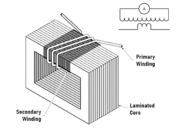
Wound CT 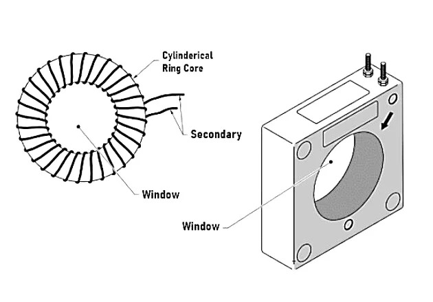
Window Toroidal CT
Applications of Current Transformers
Some of the applications for Class 3 & Class 5 current transformers for measuring instruments include:
- Overload Protection
- Control Devices
- Switchgear control and monitoring
- Current Monitoring Three Phase Generators
Potential Transformer
Potential Transformers (PT), also known as Voltage Transformers, provide an isolated secondary voltage that is in-phase and exact proportionate representation of primary voltage. Simply put, they are step-down transformers with extremely accurate turns ratio.
Connection Types on PT Secondary Winding
There are generally three types of connections for PT secondary winding:
Star Connection
Generally, a star connection winding is used for Metering and Protection Relays (Distance Relay, Directional Over Current Relay)
Open Delta Connection
Open Delta or V connection is formed with two-phase PTs. Open Delta Connection cannot be used for ground fault measurement. Ferroresonance is very low in the open-delta connection of a PT.
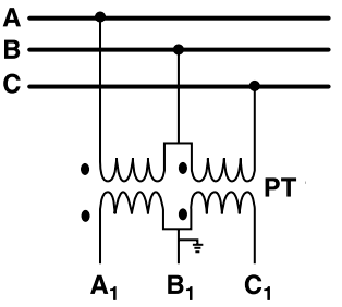
This connection is used for the measurement of line voltages and phase matching between two source voltages.
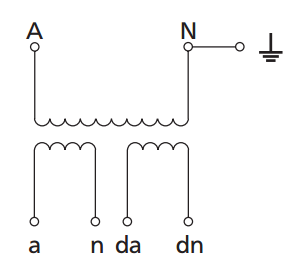
Broken Delta Connection
It is formed by using three single-phase PTs. In this type of connection, all secondary windings are connected in series.
- This connection is used to drive a Neutral Displacement Relay to detect Earth faults in non-effectively earthed systems. Earth faults cause displacement of system neutral, particularly in the case of unearthed or impedance earthed systems.
- In case of an Earth fault on the primary side, the residual voltage will be three times zero-sequence voltage.
Difference between CT and PT
The following table summarizes the major differences between a current and potential transformer:
| Type of Transformer | Current Transformer | Potential Transformer |
| No. of Windings | The secondary winding of CT has a large number of turns accurately wound for a specific turns ratio. | PT has a large number of turns in the primary and fewer turns in the secondary. |
| Property | A CT steps up (increases) the voltage while stepping down (lowering) the current. | PT step down the voltage of high magnitude to a lower voltage |
| Example | A 100:5 CT would mean the secondary current of 5 amperes when the primary current is 100 amperes. | 600:120 PT would mean the voltage across secondary is 120 volts when primary voltage is 600 volts |
| Open Circuit | Secondary of a CT cannot be open circuited | Secondary of a PT can be open-circuited without any damage caused either to the operator or the transformer. |
| Type | CT can be considered as a series transformer | PT may be considered as a parallel transformer |
| Primary and Secondary Current | The primary current in a CT is independent of the secondary circuit conditions. | The primary current of a PT depends upon the secondary circuit conditions |
| Current or Voltage | The primary winding of a CT is connected in series with the line caring the current to be measured. Hence, it carries the full line current. | The primary winding of a PT is connected across the line of voltage to be measured. Hence, the full line voltage is impressed across its terminal. |
| Applications | With the help of a CT, a 5A ammeter can measure a high current like 200A. | With the help of PT, a 120V voltmeter can be used to measure very high voltages like 11kV. |
CT and PT Solutions from Shreejee Electronics
Depending on specific application needs, our team can also offer custom manufacturing services for CTs and PTs.
With over 1,000 products in the catalog and over 35 years of experience, Shreejee Electronics is one of the leading current transformer manufacturers in India that offers a wide range of industry-leading solutions for customers across multiple industries — from renewable energy to medical — globally. In addition to our current and potential transformers, we also offer power and audio transformers and power supplies components for LED drivers.
Raise an RFQ today to see how Shreejee Electronics can help you in designing and manufacturing CT and PT.