One of the primary functions of a magnetic transformer is to provide isolation between two sections of an electronic circuit. This isolation is required to comply with a specific safety specification or protect sensitive circuits from high voltages or fluctuations. In brief, the isolation required is set by the voltage present in the circuit and the level of safety insulation that is needed. The magnetic design can ensure that the isolation requirements are met in principle. Still, the design cannot guarantee that certain defects due to variations in materials or manufacturing processes will not lead to failures over time. Therefore, it is necessary to apply some tests to the magnetic components to evaluate the integrity of the insulation.
To accurately determine the isolation capability, several semi-destructive and non-destructive tests have been established :
- Hi-pot or Dielectric Withstand Test
- Impulse test
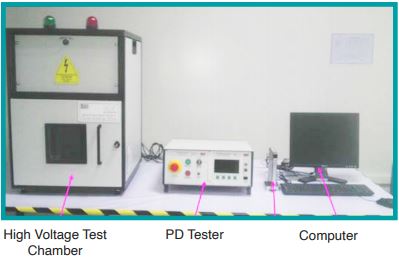
- Partial discharge test
The term ‘Hipot’ is a short form for ‘high potential,’ which is itself short for a more technical term, ‘Dielectric Withstand Test.’ Under this standard test, the electrical insulation is exposed to the high voltage over an extended time to both sides of the insulation to ensure that it meets safety and quality standards by testing the dielectric breakdown. Hipot test is the direct opposite of a continuity test. However, only carrying out hi-pot tests is not effective at identifying long-term failures.
The impulse test, which verifies if the clearances in the device would withstand specified transient over-voltages, is also not practical enough to provide data regarding the device’s real-time operating condition.
What is Partial Discharge?
According to IEC 60270 standard, partial discharge (PD) is a localized electrical discharge that only partially bridges the insulation between conductors and may or may not occur adjacent to a conductor.

Important terminologies related to Partial Discharge
Before we understand the workings of PD, let us understand some important terminology related to it:
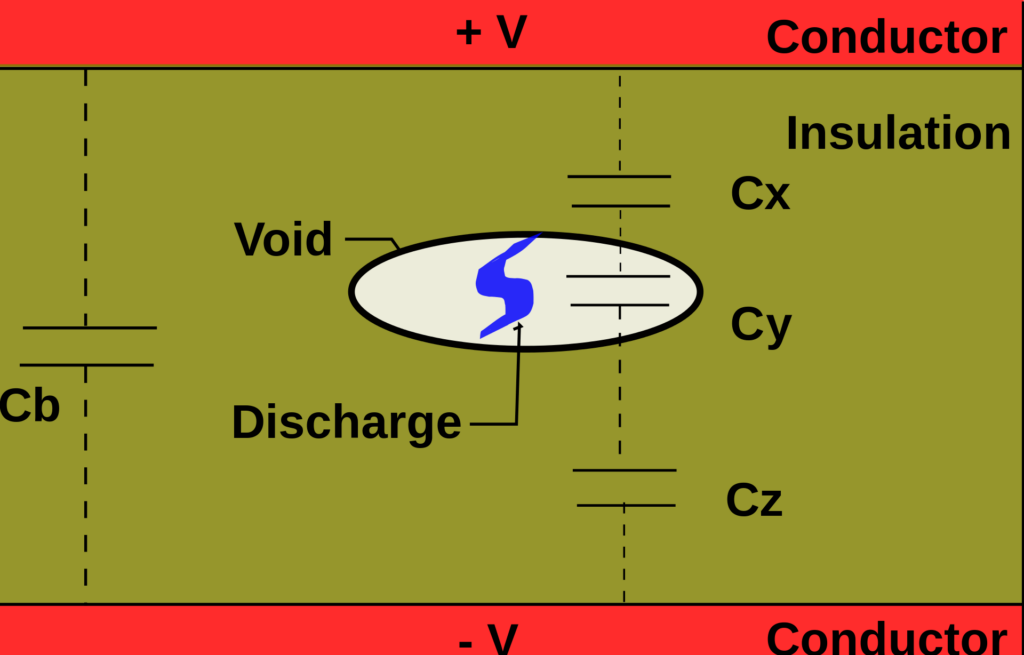
- When an isolation barrier has a fault, such as an internal void, this fault will display localized ionization when exposed to a high voltage. Localized ionization occurs when the atom or molecule acquires a negative or positive charge by either gaining or losing electrons.
- Inception voltage is the voltage at which localized ionization begins. Just when the inception voltage is reached, the ionization of void occurs, thereby shorting itself out.
- As the voltage is lowered, the ionization will continue until the extinction voltage is reached, at which point the ionization stops.
The working of a Partial Discharge Cycle
When applying a high voltage to the insulation, the voltage will also build across any voids or defects, which causes localized ionization. Ionization ceases as soon as the voltage across the void drops below the extinction voltage. This action redistributes the charge within the insulation/conductor, which is the partial discharge.
A partial discharge cycle will begin as soon as the voltage is raised again. If the voltage is AC and is high enough, partial discharge cycles will repeat many times during the positive and negative peaks.
If the Partial Discharge Testing ionization begins and continues, it can lead to the damage of the barrier, which contributes to the degradation of the insulation over time and eventual dielectric breakdown. If the discharge level is minimal, the barrier receives no damage. In such a case, the inception voltage of the individual voids remains constant.
The total charge redistributed within the barrier is an excellent indicator of the number of voids and their likelihood of becoming a failure. By setting a very low limit on the allowable partial discharge in testing transformers, a very high degree of confidence is assured that a high voltage failure will not occur with time.

Why is Partial Discharge superior to the hi-pot test?
As we know, the current required for the partial discharge to occur is very low compared to that of the current in the dielectric hi-pot test. Hence, it would not be possible to measure this long-term breakdown and insulation failure with the hi-pot test, and therefore partial discharge testing is implemented.
Therefore, knowing the maximum dielectric breakdown isolation capability of the component (hi-pot) and knowing the continuous isolation capability is highly relevant in the real-world scenario of the component’s usage.
Advantages of Partial Discharge testing
- PD helps identify defects that may have occurred during system installation or manufacturing, but it can also warn of a potential system failure by identifying insulation deterioration due to normal operating conditions early. Hence, PD is a predictive qualitative analysis tool.
- A partial discharge test is a non-destructive test since it does not result in the device under test being stressed to failure. Therefore PD test does not affect the existing insulation capability of the transformer.
- The continuous isolation capability of the component can also be easily identified using partial discharge testing.
Conclusion
In conclusion, we can say that partial discharge testing is an excellent mechanism for identifying issues with the insulation of a magnetic component. Not only can PD testing identify potential long-term problems, but it also allows the establishment of a maximum continuous voltage rating.
At Shreejee Electronics, we follow IEC 60664-1 and IEC 61800-5-1 standards when our clients require stringent processes. These standards provide a detailed process for performing the partial discharge test for various power transformers.
