
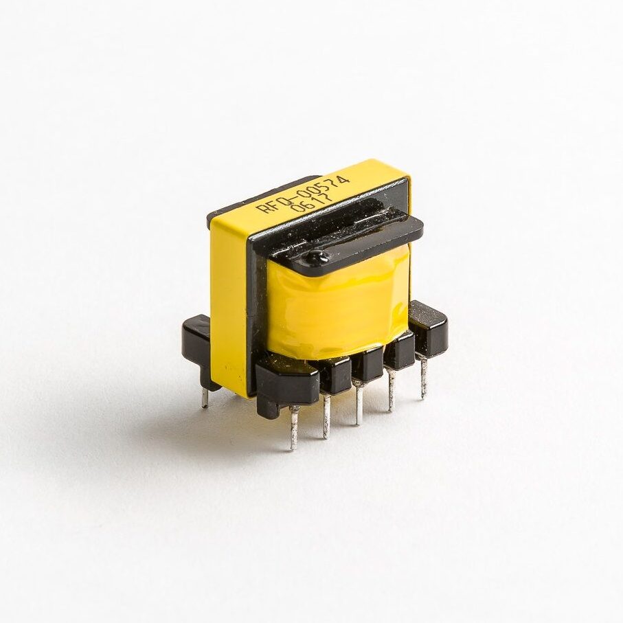
With more efficient and smaller power supplies providing power to electrical equipment, high-frequency transformers are a critical component of supplying power to modern electronics.
The market forces driving the proliferation of electronics into more and more applications result from a steady stream of design innovation that has gone unabated for more than half a century. Akin to Moore’s Law, industrial and consumer markets expect each new product iteration to provide enhanced performance, smaller size, and increased functionality. For designers, engineers, and manufacturers, this combination of factors means that choosing components that will provide optimal performance and value is more important than ever. For high-frequency transformers, understanding how to minimize losses from skin effect, proximity effect, and type of core material to use is critical. It can have a profound impact on the ultimate performance and success of a design.
High Frequency Transformers: Basic Principles
High-frequency transformers operate using the same basic principles as standard transformers. The primary difference is that, as their name implies, they operate at much higher frequencies — while most line voltage transformers operate at 50 or 60 Hz, high-frequency transformers use frequencies from 20 kHz to over 1MHz.
Operating at a higher frequency has many benefits, the first of which is size. For any given power rating, the higher the frequency, the smaller the transformer can be. Second, because the transformer is smaller, less copper wire is needed, thus reducing the losses and helping to make the transformer more efficient. Also, since the core is typically ferrite, a wide variety of geometries are available so the transformer can be tailor-made for the application. Whether additional shielding or a specific form factor is required, the chances are good that a ferrite core exists to meet the requirement.
However, the benefits brought about by lightweight, small size, and higher power density pose many challenges. Minimizing issues such as skin and proximity effects are a serious concern when designing high-frequency transformers.
Skin effects are caused by the tendency of high-frequency currents to flow on the surface of conductors. The use of Litz wire can reduce the losses due to the skin effect. Litz wire is constructed by “weaving” multiple smaller conductors together to make an equivalent larger wire gauge. For example, using 108 strands of a #40AWG is equivalent to a #20AWG. The size of each individual strand is determined by the intended operating frequency, with small strands being used for higher frequencies. The weaving process enables each strand to occupy a space near the outside (or skin) of the Litz wire at some point in the length of the wire, allowing current to flow more evenly through all strands.
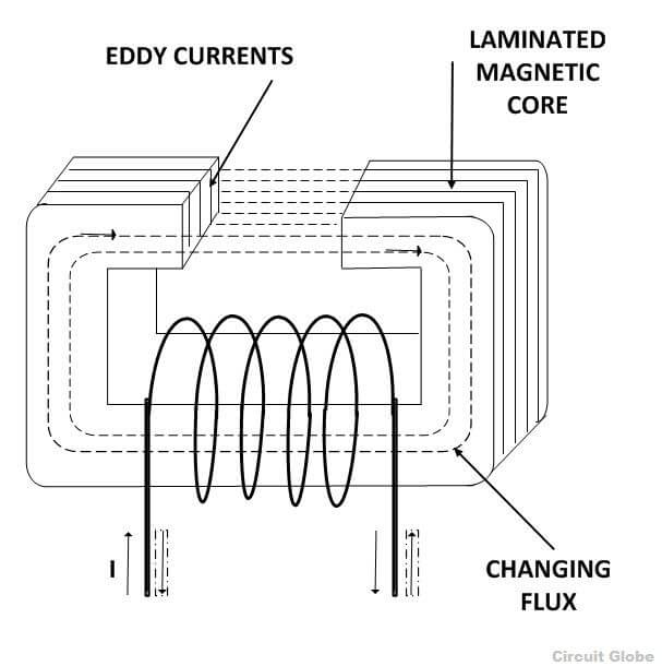
Proximity effects, also known as eddy current losses, are caused by the magnetic fields from adjacent conductors either in adjacent windings or of more serious concern in adjacent layers, which causes current to flow in unintended patterns or eddy currents. This effect creates excessive resistance within the wire and unintentional power loss. Several design considerations can minimize proximity effects, such as
- selecting a core that allows an increased number of turns/layers
- use of foil winding layers rather than round wire is another, as is interleaving the winding
Since proximity effects are a result of the magnetic-field-induced eddy currents, it should be noted that core gaps can result in losses as well. Wherever there is an air gap in the core, stray flux lines (magnetic field) extend in an arc, and as a result, proximity effects can impact the transformer winding closest to the air gap. Again, electrical designers can use several construction techniques to minimize this, such as
- using multiple gaps on the core leg, so each gap is smaller or
- using a physical barrier such as tape to keep the winding away from the gap.
As transformers become smaller, power density increases, and despite higher efficiency, heat dissipation can become a major design hurdle. In many cases, active cooling is needed either with a fan to increase airflow or by mounting the transformer on a cooling plate. Potting in a thermally conductive material is also common.
SMPS Topology
The efficiency delivered by an SMPS is critical for modern electronics and has facilitated the development of many topologies to meet many design requirements. Below are basic details of some of the most common.
Buck
Buck is a common type of topology; it is also the most straightforward and cheapest to manufacture. It is non-isolating and ideally suited to step down voltages as a DC to DC converter. DC to DC converter is a relatively simple circuit with the inductor current controlled by a transistor and diode. The downside is that to reduce the voltage ripple, output filters typically need to be added.
Boost
This topology is similar to Buck, as it is also non-isolating, but unlike Buck, Boost steps up the voltage rather down. In continuous conduction mode, it draws current relatively evenly. It is also highly customizable and applied in many applications, such as power factor correction circuits.
Buck-Boost
Buck-Boost topology is designed to both, step-down and step up the voltages and is very prevalent in battery-powered applications that provide varying input voltages. However, there are several disadvantages, the output voltage polarity is opposite the input, and input filters are needed to reduce EMI from the current ripple resulting from switching.
Flyback
Flyback provides isolation through the use of a transformer that acts as the storage inductor. The transformer provides isolation, facilitates multiple outputs, and allows for voltage adjustment by varying the turns ratio. This topology is widely used for low power applications and can also be designed for higher output voltages, but applications above ten amps should not use. With simple circuitry and no need for a separate inductor, Flyback is one of the most common topologies.
Forward
Forward topology is, in essence, a transformer isolated Buck converter and is also designed for low voltage applications. Although it offers better efficiency than a Flyback, it does use an extra inductor, making it slightly unattractive for higher output currents. However, when higher output is required, its non-pulsating output current makes it ideal for some applications of 15 amps or more.
Push-Pull
This topology is a forward converter and uses two primary windings that form a dual-drive winding. In this design, the transformer core operates very efficiently, and unlike Forward and Flyback topology, it lends itself well to being scaled up and requires less filtering.
However, switching control can be difficult, as both switches cannot be activated simultaneously. This scenario results in equal and opposite flux within the transformer, causing low impedance and high shoot-through current, potentially damaging or destroying the switch.
Essential for Off-Grid Energy Production
High-frequency transformers are an essential part of inverter circuits that allow renewable energy sources to produce usable power. Solar panels and small wind turbines store their energy in batteries that use DC voltage. However, power used for homes and businesses needs to be AC voltage. Power inverters and the transformers in them allow the DC voltage to be switched on and off and changed to a 120V AC voltage so it can be used.
Designing High-Frequency Transformers
A number of formulas are used to calculate the mechanical size of high-frequency transformers accurately; they are based on two factors: the amount of power that needs to be transferred and the operating frequency. Recent advancements such as the use of GaN diodes have facilitated increases in frequency, allowing for the development of smaller and cheaper high-frequency transformers.
For example, just a few years ago, 50-100 kHz frequency range was standard. However, today frequencies of up to 400-500 KHz and even 1 MHz are possible.
These higher frequencies have allowed transformers to shrink in size, utilizing a smaller Ae (core cross-section) for any given number of turns. In practice, design engineers must balance this equation so that as frequency increases, a smaller core and fewer turns are required to operate at the desired flux density.
Calculating a high-frequency transformer
- Choose an appropriate core.
- Calculate the primary turns needed based on the flux density the engineer chooses to operate.
- Calculate the number of secondary turns, which is represented by the ratio of primary to secondary voltage.
Additionally, when dealing with high-frequency transformers, the designer must make sure the wire thickness does not exceed 2X the skin depth at that frequency. As frequency increases, the current flows more towards the outside of the wire causing skin effect.
Not taking this into account can result in high copper losses resulting in a transformer that runs hot. As described earlier, designers can use Litz wire to mitigate this problem.
A Wide Array of Advanced Applications
High-frequency transformers are used for a wide range of advanced applications, both large and small, from powering personal computers to electricity at homes and commercial property. The product can also be used for:
- Alternative energy inverters
- Electronic switching devices
- Military Power Supplies
- LED Lighting
- Plasma Generation
- Personal electronics
Quickly search our standard range of high-frequency transformers on our catalog for your rapid prototyping needs.