
The operating frequency of many electronic circuits has been increasing since the late 1960s. The increase in frequency has decreased the size and weight of many consumer electronics available today. The frequency increase continues today, and as a result, doubts arise if there are any effects of increasing the frequency on the transformers.
This article explores:
- The consequences of increasing the frequency of transformers and inductors used in power supply applications and
- The effect of the increase in operating frequency on core losses
Effects of Increasing the Transformer’s Operating Frequency
Let us evaluate the WaAe (Window Area X Core Area product) given by Abraham Pressman’s book, “Switching Power Supply Design, 2nd Edition.”
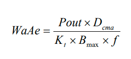
WaAe = Product of the window area and core area in cm4
Pout = Output power in Watts
Dcma = Current Density in circular mils/amp
Bmax = Flux Density in Gauss
f = Frequency in Hertz
Kt = Topology constant
Kt = 0.00100 Push Pull Kt = 0.00140 Half Bridge
Kt = 0.00140 Full Bridge Kt = 0.00050 Forward Converter
Kt = 0.00033 Flyback (Single Winding)
Kt = 0.00025 Flyback (Multiple Winding)
Keeping everything constant, except frequency and WaAe, it can be evaluated that the window area-core area product decreases as frequency increases. Alternatively, frequency is inversely proportional to the size of the transformer. As we increase frequency, the size of the transformer will decrease.
Some core vendors list the window area-core area product for their cores which becomes very handy when determining which core can be used when increasing or decreasing the frequency.
Next, engineers should evaluate the basic Faraday’s Law formula to determine the required primary turns to complete the transformer design.
Skin Effect
Skin and proximity effects are probably the two most important topics in magnetics design that cause difficulties for some engineers. Only basic concepts will be covered here as in-depth analysis of these topics is beyond the scope of this article.
The skin effect is observed when the current going through a copper wire travels on the outside “skin” of the copper than the diameter of the wire itself.
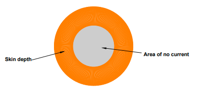
Increasing frequency leads to increased current travels on the outside “skin” of the copper, leading to an increase in AC resistance loss and temperature. (insert the reference)
Overcoming Skin Effect
Select a smaller diameter wire where the skin depth is half the diameter of the wire to reduce the losses arising out of the skin effect. However, the chosen wire diameter should still be able to handle the required continuous current.
Skin effect can be overcome by winding multiple strands of the appropriate wire diameter, thereby ensuring the capacity to handle the required current while decreasing the skin effect losses. These multiple stranded wires are commonly known as Litz wire.
Formula 2 can be used to determine the skin depth at the given application frequency.

δ = Skin depth in cm
f = Frequency in Hertz
KM = Copper Constant (7.5 at 100 ºC and 6.6 at 20 ºC)
Proximity Effect
When an AC is flowing through a conductor, it is expected that there exists an AC magnetic field flowing along the same conductor. Due to this AC magnetic field, eddy currents in adjacent turns of wire and winding layers are induced, altering the current distribution flowing through the turns of wire and winding layers. This alteration of current is known as the proximity effect. Like the skin effect, the proximity effect also leads to increased AC resistance losses and temperature rise.
Therefore, strategies like multiple strands of wire (litz) and keeping the layers of windings to two layers or less can be used to decrease the proximity effect on a conductor.
Peak-peak Ripple Current
Equation 3 should be also be evaluated when considering increasing the operating frequency to reduce inductor size. As the frequency increases, the inductance should be reduced proportionately to keep the peak-peak ripple current within the 10%-30% range (industry best practice). For example, if an existing inductor operates at 200 kHz, has 100 μH, suppose the frequency is increased to 400 kHz, the inductance should be reduced by 53 μH, an industry-standard inductance value.
This reduction in inductance will keep the ripple current within the acceptable range and allows for a reduction in size and losses. The total inductor losses decrease because of the reduction in inductance, core area, and volume.
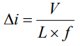
V = Voltage in Volts
L = Inductance in Henries
f = Frequency in Hertz
∆i = Peak-peak ripple current in amps
Core Loss and Increase in Operating Frequency
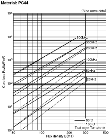
The graph in figure 2 is commonly used by engineers when designing transformers and inductors to determine the core losses. Almost all magnetic core vendors publish similar charts in their catalogs. Examining Figure 2, it would seem that the core losses increase as the frequency increases, but this is not always the case.
A careful study of the Steinmetz equation (Eq. 4), the foundation of the graph in Figure 2, needs to be analyzed to see why core loss can decrease when the frequency increases.
The Steinmetz equation consists of a constant (K1), which is available for every magnetic material. The value of K1, the Frequency exponent (X) and flux density exponent (y) can be found by consulting the particular vendor’s catalog. Typical power ferrites have a frequency exponent of 1.5 and flux-density of 2.5.
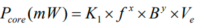
K1 = Constant for core material
f = Frequency in kHz
x = Frequency exponent
B = Peak flux density in kGauss
y = Flux density exponent
Ve = Effective core volume (cm3)
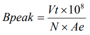
Bpeak = Peak flux density in Gauss
V = Voltage in Volts
t = Time on in seconds
N = Number of Turns
Ae = Core area of selected core in cm2
For this analysis, in equation 5, the voltage can be ignored for the time being, and since the frequency is inversely proportional to the time on it, it can be inserted into the above formula. See below for the result.
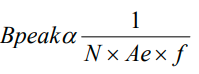
Therefore, if the frequency in equation 6 increases with the turns and core area staying constant, the peak flux density will decrease. Examining equation 4, a reduction in peak flux density will significantly impact core loss as the peak flux density will reduce exponentially by 2.5 and the frequency will increase exponentially by 1.5. Hence, it may be concluded that the core loss does not increase with an increase in operating frequency. However, core loss is evident if the core area in equation 6 is reduced and the frequency increases.
Conclusion
As evident from equation 1:
- The overall package size and core area can be reduced for transformer applications if the frequency increases.
- In order to prevent core losses from increasing, the flux density must be kept constant.
- If the core size is reduced due to increased frequency and flux density can be kept constant by increasing the turns, which may decrease the core loss. The overall volume will have decreased, which is an integral part of the core-loss equation. However, since the turns are increased, the DC resistance will increase simultaneously. Hence I2R losses must also be evaluated.
At Shreejee, we carefully review the magnetic design to optimize the transformer size while considering the various challenges presented. Contact us today for your next project.