
Fundamentally, flyback transformers are step-up transformers but with massive potential of stepping up the voltage. For an input of 230V, a flyback transformer can achieve an output of up to 20,000V. Such is the potential of flyback transformers. It can also operate with a low voltage, such as 12 V or 5V.
Let us understand some of the most commonly asked questions regarding its construction, functions, range of applications, and working principles.
Why is it called a “Flyback” transformer?
One of the earliest applications of flyback transformers was in the CRT tube. The primary winding of the transformer uses a relatively low-voltage saw-tooth wave. It can be get energized with a very low voltage. The low-voltage wave gets strengthened first and then switched off abruptly, which causes the beam on display to fly back from right to left. This peculiar property is obtained due to how the transformer functions. Hence it is called a “flyback” transformer.
Constructing a Flyback Transformer
Three simple steps to construct a flyback design are as follows:
- Wind the primary coil around a ferrite core. This coil will generate the first part of the inductor.
- Next, wind the secondary coil around the same core as the primary winding. Doing so will link the two “inductors” magnetically. To minimize leakage inductance, the secondary winding may be wounded around the primary winding. The secondary is built using a layering technique wherein the wire is layered between insulators made of polyester film. This increases the dielectric strength of the transformer and can sustain a high magnitude of voltages,
- Finally, the ferrite core is assembled to fill the magnetic flux loop gap. This gapped core allows high energy storage without saturating the core itself by increasing the magnetic reluctance.
Please note that this construction or design layout is traditional. It is supplemented with a primary switch, input and output capacitors, and output rectifiers in real-time applications.
How does a Flyback Transformer Work?
The flyback transformer’s operating principle is very similar to a conventional transformer except for its design aspects, especially the use of a gapped core. Here’s a brief on the real-time operation of a flyback transformer:
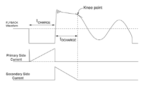
- A flyback transformer is first powered by turning on a primary switch in an integrated circuit. As the switch is turned on, the voltage gets passed via the primary winding of the transformer, which increases the primary power.
- This generated power is then stored as magnetic energy in the inductive core gap of the flyback transformer. The stored energy gets discarded after the primary switch is turned off.
- A diode is attached to the secondary winding to allow energy flow in one direction only. This diode blocks the current from flowing in the opposite direction. Once the primary switch is turned off, the secondary current flows through the diode, and the energy stored in the gap gets immediately transferred to the load.
This will complete one life cycle of a flyback transformer. This cycle is repeated after the secondary coil discharges and the current drops to zero.
If no current exists in the gap, this is called discontinuous transformer mode. If there is still some current stored in the core gap, it is called continuous transformer mode.
Typical Applications of Flyback Transformers
The flyback transformer was initially invented and used exclusively for CRT TVs and has since become helpful in advanced technology such as military aircraft. Its primary purpose is storing energy and efficiently producing high or low voltages.
Here are some common uses of flyback transformers:
- Television – The earliest flyback transformers were utilized in television sets, in which they controlled the horizontal electron beam of a CRT. Modern televisions use advanced components that produce a steady supply voltage, thanks to flyback transformers.
- Aeronautics – Many aeronautical devices are used at a precise frequency without breakdown. Flyback transformers help to deliver a steady high voltage electric supply.
- Telecommunications systems rely on flyback transformers for power and electrical supply conversion. DC to DC power conversion is typical in the telecom industry, particularly for SMPS.
- Converters and Inverters – While electrical converters and inverters operate at inconsistent frequencies, flyback transformers help them shift from low to high voltage currents. They are found in power supplies of refrigerators, computers, and air conditioners.
- Industrial Equipment – Flyback transformers support many industrial applications (motors, generators, and electrical pumps) by providing functions such as boosting efficiency and performance.
How to test flyback transformers?
Engineers can test flyback transformers for various faults:
- Engineers may use potential transformer testers to investigate any faulty windings.
- The tester will show unusual high impedance on the winding side if any open winding exists, and in the case of a short circuit, the impedance would be comparatively low.
In recent years, graphical display testers can indicate the robustness of the winding.
- Generally, a noisy operation is the result of a faulty capacitor. If measured, a noise like a tic-tac will appear on the monitor.
- The display may be blank in the case of a shorted capacitor. The capacitor needs to be replaced.
Other general problems in the transformer are shorted windings, core crackings, external arcing to the ground, etc. Engineers can test all these problems through a line-operated tester. Engineers can also use a typical multimeter to test the continuity of the circuit and measure the voltage at each point.
Considerations when choosing flyback transformers
Like any other electronic component, selecting flyback transformers involves comparing many trade-offs in performance, size, efficiency, price, and load.
Here are some critical points to consider when selecting a flyback transformer:
- Engineers must carefully select core size to achieve high energy storage without core saturating.
- To achieve high output current without the breakdown of the wire insulation, engineers must carry out a careful selection of wire size (diameter).
- To minimize the winding length, lessen cost and achieve the lowest possible DC Resistance, designers must optimize the core shape and bobbin size.
- The high switching frequency can reduce transformer size, but engineers must avoid increased AC losses from core loss, proximity effect, and skin effect.
- When higher current and power are required, forward-mode, push-pull, or half-bridge / full-bridge topologies become more efficient alternatives.
Flyback Transformers from Shreejee Electronics
Shreejee Electronics offers standard, off-the-shelf flyback transformers with power capabilities ranging from a few watts to around 120 Watts. The company also manufactures various flyback transformers in multiple shapes and core sizes, including the most common PQ and EE20 core flyback transformers.
As one of India’s eminent manufacturers of flyback transformers, Shreejee Electronics can supply flyback transformers in customized pinout configurations. Contact us today to see how we can help you with your projects.